LBL Positioning for Deepwater Subsea Structure Installation
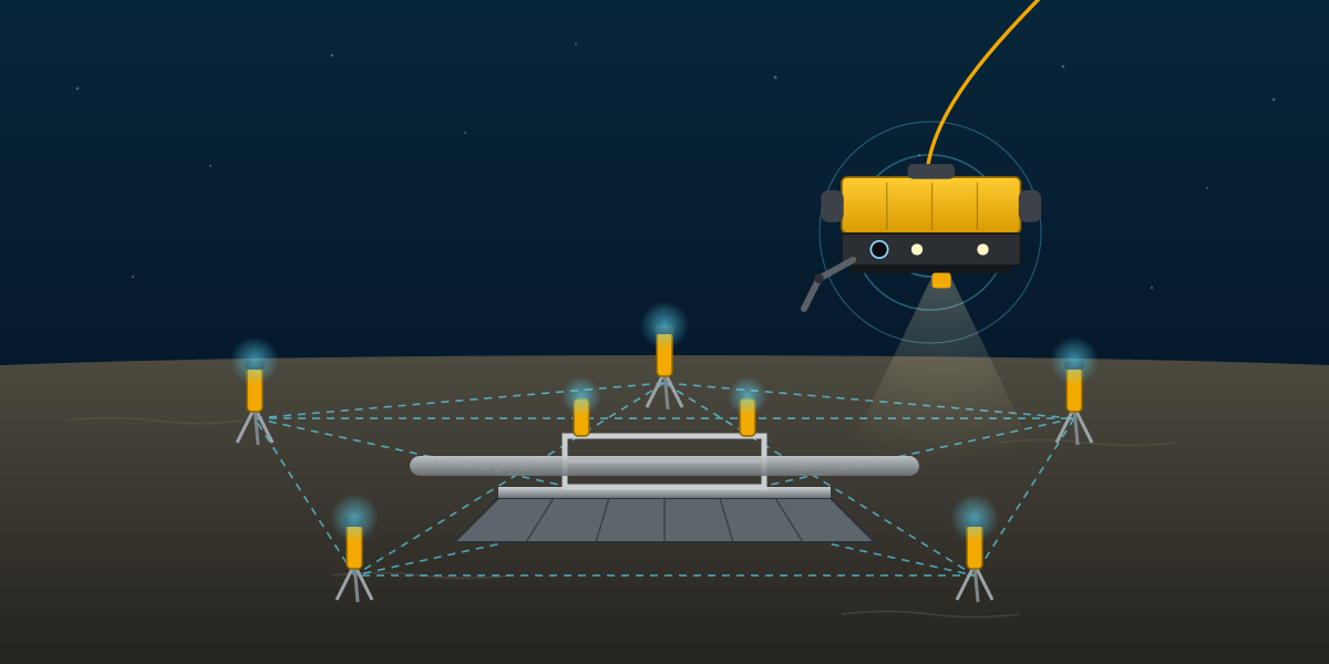
At 1,400 m water depth, the usual subsea positioning tools start to run out of accuracy. USBL from the vessel is fine for flying an ROV, but its error grows with depth, and at that depth it is easily a few metres. A subsea structure that has to land within half a metre needs something better. That is what a Long Baseline (LBL) array is for.
I was involved in a deepwater pipeline project where three mudmats, for one inline tee and two pipeline end terminations (PLETs), had to be set down in about 1,200 to 1,400 m of water. This article explains how the LBL survey procedure for that work was set up and why each step is there. Client, project, vessel and location details are left out on purpose.
Why LBL?
USBL measures range and angle from one transducer under the vessel. Small angle errors turn into large position errors at long range. LBL works differently: several transponders are placed on the seabed around the work site, the distances between them are measured acoustically, and the vehicle or structure is positioned by ranges to those transponders. Because the ranges are short and the geometry is local, the result is accurate to decimetres instead of metres.
The installation tolerances show why this was needed:
- Longitudinal position: ±10 m
- Lateral position: ±3.5 m
- Rotation: ±3°
- Inclination: ±4°
- Heading: ±3° to ±5°
- Required measurement accuracy: 0.5 m in position, 0.5° in heading and inclination
The tolerances for the structure are generous. The accuracy required from survey to prove the structure is inside them is not.
Equipment
The LBL spread was based on Sonardyne 6G equipment:
- Compatt 6 transponders, some with inclinometer and pressure (Digiquartz) end caps, some with sound velocity sensors, plus spares for each type.
- A ROVNAV 6G transceiver on the ROV.
- Fusion LBL software running on a dedicated navigation computer, with a spare system.
- Valeport mini pressure and sound velocity sensors on the ROV.
- An Octans fibre-optic gyrocompass for the ROV, with a spare.
- Seabed tripod frames and floating collars to hold the transponders.
The rule throughout was one main and one spare for every critical item. At 1,400 m, a single failed unit can stop the whole operation for a day.
Datum and conventions
Coordinates were in WGS84 on a UTM grid, with mean sea level as the vertical datum from predicted tides. The LBL scale factor in the acoustic software was set to 1, because baselines are real seabed distances, not grid distances. Raw data was logged in UTC, and reporting used local time.
Two conventions get written into procedures because they are easy to get wrong:
- Pitch and roll signs. The procedure fixed one convention (positive pitch is forward up, positive roll is port up) for every motion sensor and transponder. Every reported inclination had to be written with words as well as a number, such as "0.8° port up".
- Barometric pressure. Depth from a pressure sensor depends on atmospheric pressure. It had to be updated in the software at least every four hours, and more often if the weather changed during a dive.
Route and KP databases were entered by one surveyor and checked independently by another, with KP differences compared against grid distances.
Calibration before LBL
LBL does not replace the surface systems. It sits on top of them, so they have to be right first:
- DGPS checked with a total station at mobilisation, then primary against secondary throughout the job.
- Vessel gyro checked against a total station baseline or sun shots, and the ROV gyro offset calculated against the corrected vessel heading.
- USBL calibrated in the field by sailing circles around a seabed beacon, both clockwise and anticlockwise, with the circle radius between 40% and 100% of the water depth.
- A full water column sound velocity profile before the USBL calibration, at each new work area and at least every three days.
- A final integrity check: the ROV takes an accumulated USBL fix on an already-installed structure with known coordinates.
Installing the array
Each array had four to six transponders, spread evenly around the structure's design position, with a clear line of sight between them. At least one transponder in each array had a sound velocity sensor.
Before deployment, every transponder was inspected, tested internally and acoustically, and fitted with a centring collar at a common height. The collar was marked so any slip could be seen subsea, and the offset from the acoustic centre to the bottom of the collar was recorded. Orientation was checked too: a transponder mounted backwards will give inclination values with the wrong sign.
The transponders were lowered to the seabed on tripod frames using the vessel's deepwater lowering system, with the ROV releasing each frame and placing it where the survey team directed. Where a frame would block the line of sight between two others, the transponder was put on a floating collar instead. After each placement, about ten USBL fixes were logged to give a starting position.
Depths and sound velocity
Depth at each transponder was measured with a pressure sensor held in the ROV manipulator at the transponder's reference point. The depths were measured in a closed loop, starting and ending at the same transponder, so tide change during the loop could be removed.
Sound velocity came from the ROV sensor, logged continuously from the middle of the array, and checked against the transponders with sound velocity end caps. Baseline logging was paused about every ten minutes to update the sound speed. A small sound velocity error scales every baseline, so this is not optional.
Measuring baselines
Every transponder ranged to every other transponder, in both directions, with at least ten good ranges each way, in wideband mode. Closing sound velocity readings were taken at the end. The range histograms were reviewed and spikes removed before adjustment.
Relative and absolute calibration
A set of baselines gives the shape of the array but not its location. That takes two steps:
- Relative calibration: a least squares network adjustment with the whole array floating, which fixes the geometry in a local frame. Transponder depths are added as constraints with an allowed error of 50 mm.
- Absolute calibration: at least two transponders are tied to real-world coordinates, either by a box-in from the vessel (ranges from at least four directions around the transponder, with angles of cut close to 90°) or by placing them on a structure with known coordinates. The local array is then shifted and rotated onto the project grid.
After that, any position measured inside the array can be compared directly with DGPS and USBL positions.
Positioning the mudmats
During set-down, transponders sit in buckets on the structure, designed so the transponder is centred and returns to the same point if removed. The LBL system on the survey vessel tracked the structure as it was lowered and reported its final position, heading and inclination.
Inclination was taken from the transponders on the structure, with at least five consistent readings averaged, and used to correct the transponder position down to the structure baseplate. Corner depths were measured with the ROV-held pressure sensor to get level differences across the structure.
Checking the result
Before a position was reported, it had to pass a set of checks:
- Measured slant and horizontal ranges compared with the adjusted network ranges, within ±50 mm.
- All offsets, from transponder to structure reference point, applied in both a verified spreadsheet and a 3D AutoCAD model.
- Layout geometry checked in AutoCAD against the design.
- All computations done independently by two people, the survey party chief and the LBL lead surveyor.
Deliverables
The field report for each structure included the transponder list (serial numbers, addresses, battery state), structure position, heading and inclination, the sound velocity observations, seabed profiles along and across the location, and a summary of events. The DTM was delivered in GIS-ready formats (ArcASCII grid and GeoTIFF).
What I took from this procedure
- In deep water, accuracy comes from geometry and redundancy, not from one good sensor. Short baselines, many ranges, both directions, two people computing.
- Sound velocity and pressure are survey measurements in their own right. Most LBL errors trace back to one of them.
- Write conventions down and say them in words. A sign error in pitch or roll can put a structure "within tolerance" when it is not.
- Plan the spares. In deep water, recovering a failed transponder costs ROV time, and ROV time is the most expensive thing on the vessel.
- Coordinate with everyone in the field. Several contractors were using acoustic systems at the same time, so transponder frequencies and addresses had to be agreed in advance to avoid interference.