Planning a Multi-Scope Survey and Positioning Services Package
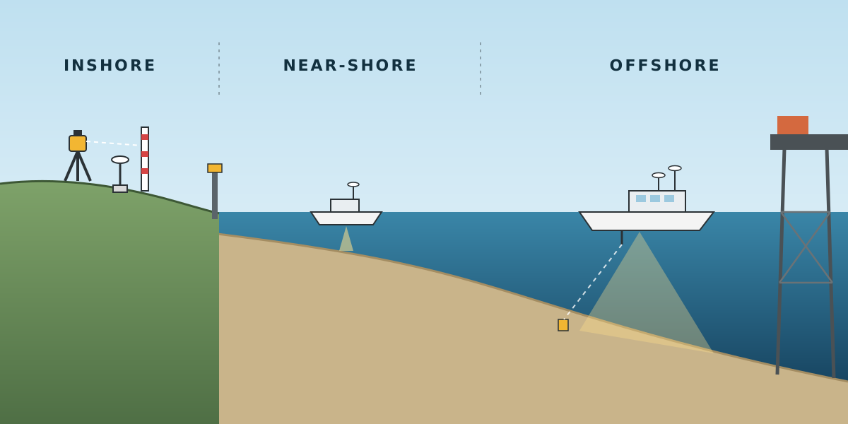
Most survey proposals cover one job: a rig move, a pipeline route, a bathymetric survey. Some cover a whole package of survey services for an operator, called off one task at a time over the length of a contract. Those are a different kind of document. You are not planning one survey. You are planning a service that has to be ready for twenty-odd different surveys, on land, in shallow water and offshore, without knowing which one will be called first.
This article is based on a project execution plan (PEP) I prepared for a topography and positioning services package for an oil and gas operator. It sets out how the survey contractor would run the package: the areas, the service lines, the team, mobilisation, calibrations, methodology and reporting. Client, project, field and location details are left out. Later articles in this series will look at the main groups of services in more detail.
Three kinds of site
The scope split the work area into three zones, and almost every decision in the plan follows from that split:
- Inshore: the land and swamp area, including river banks and delta channels.
- Near-shore: from the shoreline out to roughly 4 nautical miles.
- Offshore: anything beyond roughly 4 nautical miles.
Elevations and water depths across the sites ranged from a few hundred metres above chart datum down to around 150 metres below it. One package therefore had to cover levelling on land, singlebeam work from a small boat in a delta channel, and multibeam and USBL work from a vessel offshore. The plan also had to leave room for "other areas as requested", which in practice means the conditions are not fully known when the plan is written.
Twenty-six service lines, four families
The scope listed 26 separate services. Reading them one by one, they fall naturally into four families, and it helps to plan them that way:
- Positioning support: swamp rig moves, offshore rig moves, barge and vessel positioning, and positioning and monitoring for platform, pile and pin connector installation.
- Geodetic control and topography: GNSS static observation for reference points, precise levelling, reconnaissance, RTK DGNSS survey, traversing and WADGNSS survey.
- Hydrographic and pipeline survey: general bathymetry and object marking, multibeam bathymetry, pipeline inspection, pipeline route survey and seabed clearance, each in a near-shore version and an offshore version.
- Data and analysis: tide observation, tide analysis and prediction, metocean analysis, platform settlement and deformation monitoring, and setting temporary markers. On-call equipment and personnel services sit alongside these.
Each service line in the plan has its own equipment table and its own crew list. That looks repetitive on paper, but it is what the client needs: when a task order arrives for one service, both sides can see exactly what spread and which people come with it.
The equipment scales with the water
The most useful part of writing the equipment tables was seeing how the spread grows as the work moves offshore. The same type of survey needs very different kit depending on where it is done.
A near-shore general bathymetry survey needs little more than DGNSS, a fluxgate compass, a singlebeam echo sounder, a shore tide gauge and some marker buoys. Add multibeam and you need a gyro and a CTD profiler for sound velocity. A near-shore pipeline inspection adds side scan sonar and a magnetometer, because the pipeline has to be found as well as measured.
Offshore, the same pipeline task grows again. An offshore pipeline route or seabed clearance survey carries a gyro, singlebeam, multibeam, side scan sonar, sub-bottom profiler, magnetometer, USBL with a transponder, CTD, a transducer pole and a three-phase generator to run it all. That is a full geophysical spread, not a boat with an echo sounder.
The land and control tasks are lighter in hardware but heavier in accuracy: GNSS receivers for static sessions, a total station for traversing, digital levels with staffs and atmospheric sensors for precise levelling, and plenty of monument material for new bench marks.
The crew scales the same way
Crew lists follow the same pattern. Every service runs 24 hours, so the people come in pairs or shift sets:
- Rig move and barge positioning: two surveyors, two positioning engineers and two helpers.
- Pile and connector monitoring, and GNSS static work: two topographic surveyors and two assistants or helpers.
- Near-shore bathymetry: one surveyor, one positioning engineer and helpers, with a multibeam engineer added when multibeam is used.
- Near-shore pipeline work: a geophysicist joins the team to interpret side scan and magnetometer data.
- Offshore pipeline and clearance work: two surveyors, two geophysicists, a multibeam engineer, two positioning engineers, helpers and a data processor.
- Analysis services: a different profile altogether, with hydrographic and geodetic engineers, oceanographers, meteorologists and data analysts working onshore.
The plan also sets minimum requirements for everyone: suitable experience and education, a valid offshore medical, sea survival training (BOSIET or FOET), and a passport.
Who does what
The roles section is short, but it makes the line of responsibility clear:
- The party chief is the senior person in the field: keeps the team on scope, raises any deviation with the project manager, reviews data, collates daily reports, oversees calibrations and prepares the final report.
- The surveyor installs, calibrates and runs the equipment, plans lines against the field layout, guides the helmsman and checks every offset and correction setting.
- The survey engineer keeps the systems working, holds spares, and raises a non-conformance when something fails.
- The data processor and geophysicist turn raw records into results.
Above them sit the project manager, the HSSE manager and the client site representative.
Mobilisation
All logistics run through one main port, coordinated with the client's base camp. Before anything moves there is a pre-mobilisation list: project documents, equipment lists, a kick-off meeting, equipment audits, testing and certification, procurement and logistics.
At mobilisation, a pre-project meeting with everyone involved covers the job, the vessel and its HSE rules, responsibilities, the emergency response plan, hazard identification, required calibrations, and processing and reporting requirements. Demobilisation starts only when the client confirms in writing that the survey is complete.
Calibrations come first
The plan is firm that no survey data counts until the spread has been verified, and that every result goes to the client representative for approval:
- DGNSS verification: a static comparison against known control points on the wharf, with an elevation mask of 10 to 15 degrees and at least four satellites. If there is no control on the wharf, the surveyor sets up two points first. The mean difference must be within 1.0 m, with a standard deviation under 0.5 m.
- Gyro calibration: primary and secondary gyros checked against a baseline on the quay with a total station. Calculated minus observed (C-O) gives the correction, with grid convergence applied if the quay heading is a grid bearing.
- Offsets: every sensor measured from the common reference point by total station or tape, using one sign convention (X to starboard, Y forward, Z up) throughout.
- Sound velocity: a wet test before mobilisation, and manufacturer calibration traceable to a standard.
- USBL: a transponder on the seabed in more than 50 m of water, a sound velocity profile, six lines around it at two to three times the water depth, and a check run from four corners afterwards to prove the corrections.
Methodology in one page
The methodology is deliberately brief, because the detail sits in each task procedure. The key points are:
- All data is time-tagged from the GNSS pulse-per-second signal.
- Positioning is quality-checked in the navigation software before it is passed to the USBL.
- The online system logs every raw sensor, computes positions at least every two seconds, displays the field layout for the helmsman and the client, and prints any non-conforming event.
- One data processor per shift processes data onboard, using the client's file naming. Raw and processed data are both kept, and processing can be repeated and audited.
Reporting
Reporting is layered so that the client always knows where things stand:
- A mobilisation report with DGNSS verification, gyro calibration, offsets and function tests.
- A survey log and QC log, kept by the online surveyor and copied to the client every day.
- Daily progress reports, signed by the client representative.
- A preliminary field report when acquisition ends.
- A final survey report that brings all of the above together, in PDF and in editable formats.
Risks named in advance
The plan ends with a short risk table: weather, equipment failure, mobilisation delays, personnel shortages, data loss, inaccurate tide or metocean instruments, poor communications and scope creep. Each has a plain mitigation, such as calibrated spares, redundant backups, satellite communications, a backup for each key role, and written approval for any scope change. The party chief and project surveyor review the list before work starts, and it is repeated in toolbox talks and shift handovers.
What I took from it
- Group the scope before you plan it. Twenty-six services look unmanageable as a list. Four families with a clear pattern are much easier to plan, price and staff.
- Let the site drive the spread. The jump from near-shore to offshore is not a bigger boat with the same equipment. It is a different survey.
- One table per service is worth the repetition. When a task order arrives, nobody should have to work out what to send.
- Put acceptance numbers in the plan. A 1.0 m limit for DGNSS verification is something both sides can check. "Verify the DGNSS" is not.
- Write the risks down early. Most of them are not surprises, and writing them down means someone is responsible for them before they happen.